
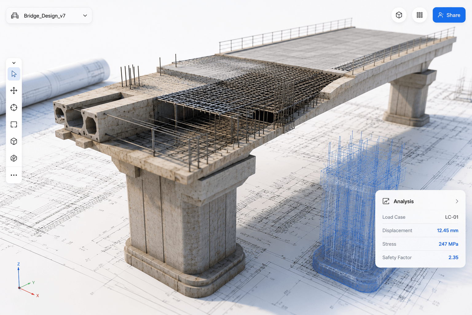
Project overview
Where engineering setup meets expert judgement.
Clariti supports civil and structural engineers working with cast-in channels, T-bolts, anchor systems, concrete slabs, masonry supports, and related structural products. The redesign had to reduce setup effort without obscuring the technical logic engineers needed to verify.
How to read the case study
A useful intersection
A project grounded in engineering.
My Mechanical Engineering background and experience with Fusion 360 helped me understand the relationship between interface design, 3D geometry, loads, simulation, and engineering judgement.
Redesign the product around expert control.
- 01Product strategy and experience architecture
- 02AI interaction and approval flows
- 033D workspace and contextual editing
- 04Product, load, simulation, and reporting workflows
- 05Technical prototyping and design-system components
The redesign brief
From form-heavy setup to guided model creation.
The existing application required engineers to move through multiple screens, forms, dropdowns, and configuration steps before reaching a useful model. The redesign explored how AI could create a credible starting point while keeping the underlying engineering visible.
- 01Open product
- 02Complete forms
- 03Choose product
- 04Configure parameters
- 05Run calculation
- 06Export report
- 01Describe intent
- 02Create starting point
- 03Review in 3D
- 04Edit and simulate
- 05Understand results
- 06Approve and report
The central design question
How could Clariti reduce setup without hiding engineering logic?
Core product principle
AI should reduce engineering effort, not replace engineering judgement.
AI product direction
AI as a working layer, not a chatbot.
I designed the assistant to help create models, request missing information, explain results, and prepare changes. Any action affecting the design remained visible and subject to review.
“Design a concrete slab with M20 bolts under 18kN shear.”Illustrative prompt based on the intended interaction model
Review → Simulate → Understand
A visible control model
Four modes make AI authority explicit.
Manual
No AI changesEngineers edit the model directly. AI makes no changes.
Ask Clariti
Explain onlyExplains the model and results without changing either.
Command Clariti
Review requiredPrepares a requested change for review and approval.
Copilot
Proactive suggestionsA future concept for proactive suggestions, with engineer review retained.
The workspace
Models, parameters, AI, and results in one place.
I brought the active model, component parameters, assistant, simulation state, and results into one workspace. The interface revealed the context required for the current engineering decision instead of displaying every control at once.
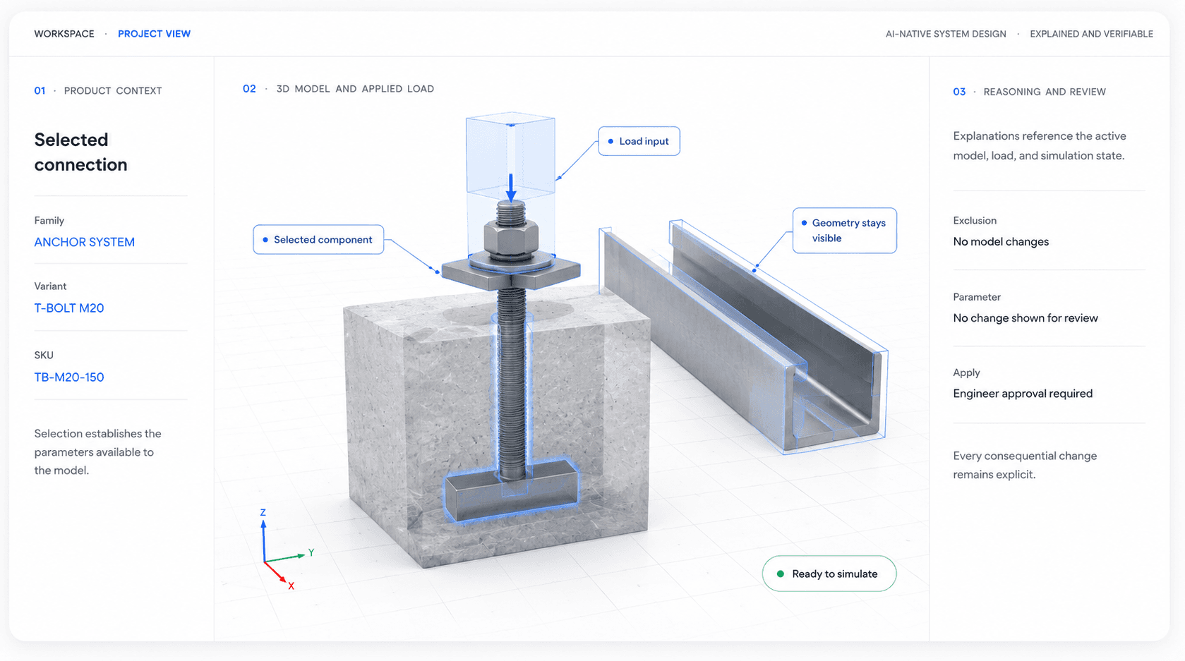
High-fidelity prototypes clarified system behaviour.
I used Vercel V0 to explore layout, responsive behaviour, component states, and the relationship between the model, assistant, parameters, and results. V0 helped express and test the direction. It did not replace engineering implementation or structural validation.
Engineering workflows
A shared structure for products, components, and loads.
Product selection, component parameters, loads, bolts, and simulation inputs affect one another. I designed these workflows around that shared model rather than presenting them as unrelated forms.
Product hierarchy
From product family to calculation-ready SKU.
- 01 · Product typeCast-in channel
- 02 · FamilyCPRO
- 03 · VariantCPRO38
- 04 · SKUCPRO38-200
Selecting the SKU establishes the product data used by configuration, calculation, simulation, and reporting.
Contextual editing
Edit the selected component in context.
Load configuration
Keep applied forces tied to geometry.
- 01Channel
- 02T-bolts
- 03Bolt positions
- 04Applied loads
- 05Simulation checks
Configuration, physical location, and calculated effects remain connected.
Multiple-bolt editing
Review repeated bolt data together.
This spreadsheet-style concept let engineers compare positions, shared values, and individual loads without opening each bolt separately.
Exploratory concept · Not presented as shipped functionality| Bolt | Position | Shear | Tension |
|---|---|---|---|
| B01 | 0 mm | 18 kN | 4 kN |
| B02 | 120 mm | 18 kN | 4 kN |
| B03 | 240 mm | 18 kN | 4 kN |
Results and trust
Results that explain what happened and why.
Simulation feedback remained inside the workspace so engineers could inspect the overall status, identify the governing check, understand its cause, and decide whether to review a proposed change.
- 01Configure
- 02Simulate
- 03Review status
- 04Inspect governing check
- 05Review proposed change
- 06Approve and rerun
One primary check needs review.
Connect the governing check to its inputs.
The explanation links the result to the active geometry, load, material, and component configuration so the engineer can judge the next action.
Engineers must verify every consequential input and change.
AI proposes. Engineers decide.
Experts retain accountability and can defend the resulting calculation.
Report structure
Understand in context, then export.
- 01Design context
Summary, parameters, and materials
- 02Engineering verification
Tension, shear, combined checks, concrete, and reinforcement
- 03Decision record
Applied changes, fixes, and final status
PDF remained the primary report format. JSON and Markdown were future directions, not delivered outcomes.
07 · Outcome and reflection
A clearer direction for AI-assisted engineering.
I designed a connected product direction spanning intent-led model creation, manual 3D editing, explicit AI modes, component configuration, load workflows, simulation results, reviewable fixes, and reporting.
The project reinforced that expert AI products do not create value through autonomy alone. They create value by helping people navigate complexity with better context, clearer options, and confidence in every consequential action.
AI becomes useful in engineering when it makes expert judgement easier to apply, inspect, and defend.